


Hoverboard Motherboard Diagram – Understand Your Board’s Core System
A hoverboard motherboard diagram is the key to understanding how your hoverboard functions at its core. It shows the detailed layout of circuits, chips, and connections that manage power, balance, and motor control. By studying this diagram, you can easily identify parts, trace signal paths, and perform safe repairs or modifications. Whether you’re troubleshooting or customizing your ride, knowing the motherboard system helps keep your hoverboard running smoothly and efficiently.
What Is a Hoverboard Motherboard Diagram?
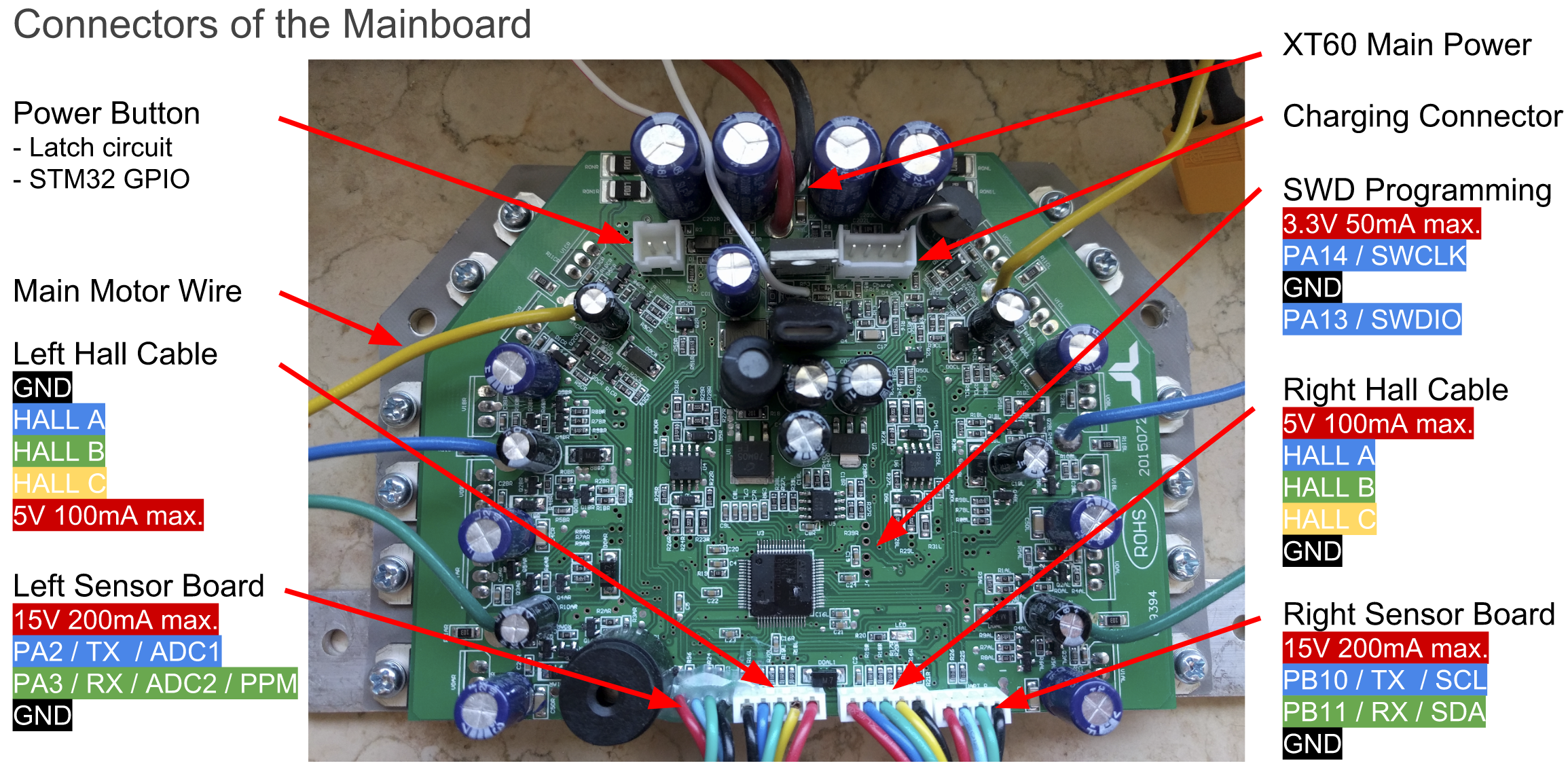
Image Source: https://github.com/
A hoverboard motherboard is the central control unit that manages all key functions of a hoverboard — including motor control, power flow, balance detection, and sensor communication. It acts as the “brain” of the hoverboard, processing input from the gyroscope and accelerometer to maintain balance and stability. Every acceleration, turn, or stop command goes through the motherboard before reaching the motors.
A hoverboard motherboard diagram is a technical drawing that illustrates how these components are connected and interact. It shows the layout of circuits, chips, and connectors such as power input lines, communication ports like UART or I2C, and motor driver outputs. This diagram serves as a visual guide to understand how electricity and data flow throughout the hoverboard.
Having a clear hoverboard motherboard diagram is extremely helpful for anyone working on DIY projects, repairs, or firmware modifications. It helps identify component positions and pinouts, making it easier to fix damaged boards or perform upgrades. For enthusiasts, it also enables reprogramming of the motherboard to create innovative projects such as electric carts, balance robots, or custom vehicles.
In troubleshooting, the motherboard diagram helps trace faults, test voltage levels, and confirm circuit connections. Whether you are flashing new firmware or diagnosing a malfunction, knowing the hoverboard motherboard diagram ensures that repairs and modifications are done safely and effectively.
The Role of the Motherboard in a Hoverboard
The hoverboard motherboard is the main control unit that links the motors, battery, and sensors together. It continuously processes data from the gyroscope and accelerometer to keep the hoverboard balanced and responsive. Every move—accelerating, turning, or braking—is managed by the motherboard through precise motor control.
It also manages power distribution and safety by regulating voltage, preventing overloads, and ensuring smooth communication between both wheels. Without the motherboard, the hoverboard cannot maintain stability or respond properly to the rider’s actions.
A hoverboard motherboard diagram typically highlights these major components:
-
Microcontroller (MCU): The brain of the hoverboard that processes sensor data and controls motor behavior.
-
Motor Driver Circuits: Convert low-power control signals into high-current pulses that drive the motors.
-
Power Management System: Includes MOSFETs and voltage regulators that stabilize the power supply and protect circuits.
-
Communication Ports (UART, I2C, ADC): Allow connections for sensors, Bluetooth modules, and firmware tools.
-
Sensor and Safety Connectors: Link the mainboard to gyroscopes, LEDs, and protection systems.
Understanding the hoverboard motherboard layout through its diagram helps with DIY customization and repairs. It allows users to locate faulty components, test signal paths, and make safe modifications. For developers, it also opens up opportunities to repurpose hoverboard hardware for creative motorized or robotic projects.
Hoverboard Motherboard Connections Explained
The hoverboard motherboard is designed with multiple connection points that allow communication between the main control board, motors, and sensor units. Among the most important are the two 4-pin cable connections, which originally link to the hoverboard’s sensor boards. These connectors are vital for transferring power and data across different components, ensuring smooth and synchronized operation of the entire system.
Each 4-pin cable carries specific signals that enable both power supply and communication:
-
GND (Ground): Serves as the electrical return path for the circuit, ensuring voltage stability and safe operation.
-
12/15V Line: Provides power from the mainboard to the connected sensor boards and accessories.
-
USART2 and USART3: These are communication ports that transmit and receive data between the mainboard and external devices or controllers.
These ports can be configured for different communication modes such as UART (Universal Asynchronous Receiver-Transmitter) and I2C (Inter-Integrated Circuit), which are common protocols used for data exchange in embedded systems. UART is typically used for serial communication, allowing devices to send and receive data efficiently, while I2C supports multiple devices through shared connections, making it ideal for linking sensors or input controllers.
In addition, the motherboard pins PA2 and PA3 can also function as 12-bit ADCs (Analog-to-Digital Converters). This means they can interpret analog signals—like those from potentiometers or variable sensors—and convert them into digital data for the microcontroller to process. This versatility allows the hoverboard motherboard to be repurposed for a wide range of applications beyond personal transport, such as robotic systems or motion-controlled devices.
When looking at a hoverboard motherboard diagram, you can clearly see how these connections are arranged around the main control chip and power circuits. The diagram helps identify which pins correspond to each communication line, making it easier to connect custom peripherals or troubleshoot faulty wiring. Understanding these connections is essential for safely modifying firmware, building new projects, or diagnosing data transmission issues within the motherboard.
Troubleshooting Common Hoverboard Motherboard Issues
Even reliable hoverboard motherboards can face technical issues after flashing firmware or during operation. Most problems come from power supply errors, wrong connections, or signal interference. Below are the most common issues and how to fix them quickly using the hoverboard motherboard diagram as your guide.
1. Firmware Flashing Problems
Sometimes the hoverboard won’t flash correctly or powers off during the process. This usually happens if the board isn’t properly powered or the power button isn’t pressed during flashing.
Quick Fix:
-
Make sure the battery voltage is above 36V while flashing.
-
Never power the mainboard from the programmer’s 3.3V line — it can damage the board.
-
Check all pins and ground connections using the motherboard diagram before flashing again.
2. Motor Not Rotating Smoothly
If the motors vibrate, jerk, or spin unevenly, the issue may be incorrect motor phase mapping. Some hoverboards use different color wire layouts, which can cause confusion.
Quick Fix:
-
Verify the motor phase wires match correctly (e.g., blue-blue, yellow-yellow, green-green).
-
If the motor still runs rough, try swapping two phase wires.
-
Refer to the hoverboard motherboard diagram to confirm correct motor connections.
3. Nunchuck or PPM Controller Not Responding
Unresponsive controllers or delayed inputs usually mean there’s signal interference or unstable voltage on the I2C or PPM lines.
Quick Fix:
-
Keep controller cables short and use shielded wires.
-
Add I2C pull-up resistors and ferrite beads to reduce noise.
-
Use around 100kΩ resistors between ADC inputs and ground to stabilize signals.
4. High Idle Current or Power Drain
If the board draws too much power when idle, it may point to faulty MOSFETs, damaged capacitors, or short circuits in the power circuit.
Quick Fix:
-
Use a multimeter to check current flow across the board.
-
Follow the hoverboard motherboard diagram to trace voltage paths.
-
Replace any component showing abnormal resistance or heating.
5. Why the Diagram Matters
A detailed hoverboard motherboard diagram makes troubleshooting faster and safer. It shows where each connection, capacitor, or IC chip is located, helping you test and repair specific areas with confidence. Whether you’re fixing firmware errors, motor issues, or signal noise, using the diagram ensures accurate diagnosis and a smooth repair process.
Don’t have a hoverboard yet? Check out iHoverboard
|
Specification |
|||||
|
Image |
 |
 |
 |
 |
 |
|
Regular Price |
£159.99 |
£199.99 |
£105.99 |
£309.99 |
£319.99 |
|
Sale Price |
£78.99 |
£104.99 |
£105.99 |
£148.99 |
£158.99 |
|
Wheel Size |
6.5" |
6.5" |
6.5" |
8.5" |
8.5" |
|
Motor Power |
Dual 350W |
Dual 250W (500W) |
Dual 350W (700W) |
Dual 400W (800W) |
Dual 400W (800W) |
|
Battery Capacity |
25.9V 2.6Ah |
36V 2Ah |
36V 2Ah |
36V 4Ah |
36V 4Ah |
|
Top Speed |
6.8 mph (11 km/h) |
7.5 mph (12 km/h) |
7.5 mph (12 km/h) |
7.5 mph (12 km/h) |
9.3 mph (15 km/h) |
|
Range / Ride Time |
40–60 min |
50–70 min |
7.5 miles (12 km) |
Up to 12.4 miles (20 km) |
Up to 12.4 miles (20 km) |
|
Charging Time |
2–3 h |
2–3 h |
2–3 h |
4–5 h |
4–5 h |
|
Max Weight |
119 lbs (54 kg) |
220 lbs (100 kg) |
200 lbs (100 kg) |
220 lbs (100 kg) |
220 lbs (100 kg) |
|
Age Recommendation |
3+ |
6+ |
6+ |
6+ |
6+ |
|
Tire Type |
Solid rubber |
Solid rubber |
Solid rubber |
Solid off-road tire |
Solid off-road tire |
|
Self-Balancing |
Yes |
Yes |
Yes |
Yes |
Yes |
|
Bluetooth Speaker |
Yes |
Yes |
Yes |
Yes |
Yes |
|
LED Lights |
Multicolor wheels & deck |
LED wheels & body |
LED light up deck & wheels |
LED wheels + body lights |
LED wheels + body lights + RGB side lights |
|
App Control |
No |
No |
No |
No |
Yes |
|
Riding Modes |
1 Mode |
3 Modes (8/10/12 km/h) |
1 Mode |
3 Modes (8/10/12 km/h) |
2 Modes (10/15 km/h) |
|
Climbing Angle |
N/A |
N/A |
N/A |
Up to 10° |
Up to 10° |
|
Product Weight |
10.1 lbs (4.6 kg) |
12.6 lbs (5.7 kg) |
14.3 lbs (6.5 kg) |
14.3 lbs (6.5 kg) |
14.3 lbs (6.5 kg) |
|
Water Resistant |
Yes |
Yes |
Yes |
Yes |
Yes |
|
Go Kart Compatibility |
No |
K3 Go Kart |
K3 Go Kart |
K3 Go Kart |
K3 Go Kart |
Conclusion
Understanding the hoverboard motherboard diagram is essential for anyone looking to maintain, repair, or customize their hoverboard. By familiarizing yourself with the mainboard’s layout, including power circuits, motor drivers, communication ports, and sensor connections, you can troubleshoot issues more efficiently and perform firmware updates safely. This knowledge also opens up opportunities for creative DIY projects, from motorized chairs to self-balancing robots. Using the diagram as a guide ensures every modification or repair is precise, helping you get the most out of your hoverboard’s performance and longevity.


Still, need help? Contact Us: support@ihoverboard.com
What's the option? Check out the option now!
Leave us a message